Rotary encoder
In this tutorial we are going to use the ESP32's pulse counter to read a rotary encoder.
A rotary encoder is usually a wheel or a knob that turns freely without any limits or stops. (Picture)
Typically a rotary encoder has two output signals:
- CLK (sometimes called A)
- DT (sometimes called B)
These two signals create square-wave pulses as you rotate the knob:
Clockwise rotation: (CLK leads DT)
Counter-clockwise rotation: (DT leads CLK)
Put simply, if we look at the 'rising edge' (the first moment the CLK goes up), we can check to see what the state of the DT pin is. If DT is low when CLK rises, the encoder is turning in one direction. If DT is high when CLK rises, then its being turned the other way.
On many platforms, we have to manually code states that track these and act on those using logic with a timer. The ESP32 platform has a hardware pulse-counter module (PCNT) onboard which Toit exposes using the 'pulse-counter' library.
Using this peripheral we can simply tie our rotary encoder pins to this module to help us track 'intents', a single click of rotation. Our code can then watch that counter to determine what is happening with those rotations.
Prerequisites
We assume that you have set up your development environment as described in the IDE tutorial.
We also assume that you have flashed your device with Jaguar and that you are familiar with running Toit programs on it. If not, have a look at the Hello world tutorial.
Setup
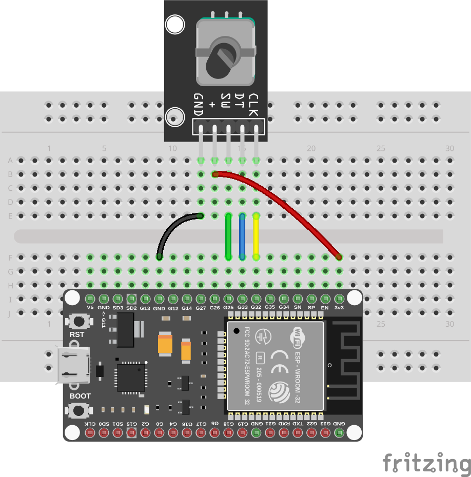
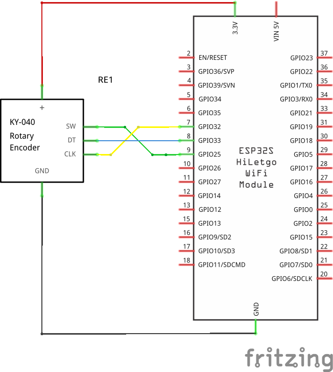
Connect your rotary encoder KY-04 (or similar) as follows:
- CLK (or A) to pin 32.
- DT (or B) to pin 33.
- SW (or switch) to pin 25 (optional, if your encoder has a push-button).
- 3.3V to the + (or VCC) pin of the encoder.
- GND to the GND pin of the encoder.
Take care if using your own unmounted encoders as soldering irons can easily harm the components inside.
Code
Create a new file rotary.toit and put the following code into it:
import gpio
import pulse-counter show Unit Channel

CLK-PIN ::= 32
DT-PIN ::= 33
SW-PIN ::= 25

main:
  // Set up the pins and the counter.
  clk := gpio.Pin CLK-PIN
  dt := gpio.Pin DT-PIN
  sw := gpio.Pin SW-PIN --input --pull-down

  // Since we only need one channel, we can just configure the channel while
  // creating the pulse counter. If multiple channels are changing a
  // counter (unit), then we would need to create a list of channels and pass
  // that to the pulse-counter.Unit constructor.
  counter := Unit clk --control-pin=dt
      --on-positive-edge=Channel.EDGE-INCREMENT
      --on-negative-edge=Channel.EDGE-DECREMENT
      --when-control-low=Channel.CONTROL-KEEP
      --when-control-high=Channel.CONTROL-INVERSE

  // Start the counter.
  counter.start

  last-count := counter.value

  while true:
    // Read the current count.
    current-count := counter.value

    // If the count has changed, print the new value.
    if current-count != last-count:
      direction := (current-count > last-count) ? "clockwise" : "counter-clockwise"
      print "Rotated $direction: $current-count"

    if sw.get == 0:
      counter.clear
      print "Button pressed (counter cleared)"

    // Sleep for a short while to avoid busy-waiting.
    sleep --ms=100
    last-count = current-count
This code allocates a pulse counter unit with one channel. Using the
--on-positive-edge and --on-negative-edge options we tell the pulse counter
to increment the counter when the CLK pin goes high, and decrement it when it
goes low. If the encoder is turned in one direction the control pin switches
polarity between these two events, and the counter thus continuously counts
up or down.
For simplicity we use polling to detect when the switch is pressed. One could
also use a task and gpio.Pin.wait-for to detect the switch press asynchronously.
There is currently no way to detect changes in the counter asynchronously. If
pins are free, then just connecting CLK to a second pin and using
wait-for to detect changes in the counter is a simple work-around.
Exercises
- Combine the rotary encoder and the SSD 1306 display to show a counter that increments and decrements as you turn the encoder.
- Use asynchronous tasks to detect the switch press and the counter changes.